

 1.4.11 - Norsk Data complete systems
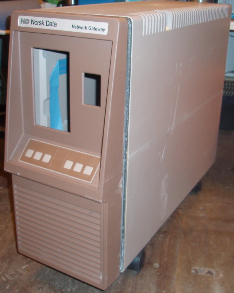
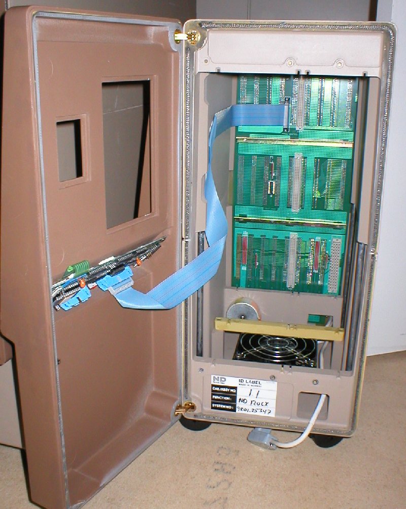
0 - The machine and its conditionThis machine was partly dismounted when I come to its rescue. All the parts seem to be present but some parts were in a terrible shape, rusty and dirty. All the pieces were gently put together and then I wonder; should I apply power to the machine now and watch what will happen or not? I decided to try to put power on the machine. When I switch the power on the fans and disc start spinning, light in the panel came on and then ALERT smoke is coming out of the cabinet. The power was quickly disconnected, but was any seriously damage done? |
|
|||||||||||||||||||||||||||||||||||||||||||||||||||||||||||||||||||||||||||||||||||||||||||||||||||||
|
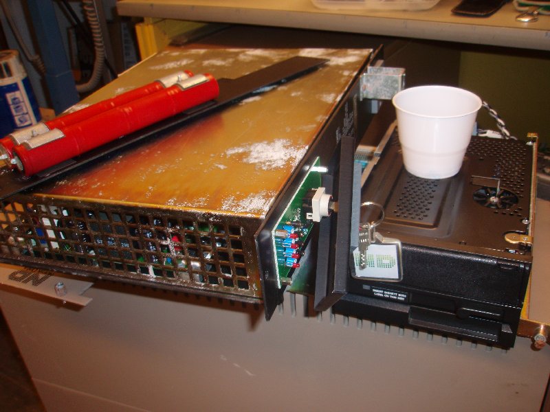
The ND Satellite was taken home and dismounted. Except for the rust, dirt and some scratches there were none visible damages after my quick test, however a broken wire on the power supply was found. It may have been the smoking gun, time will show. The power supply seems to be the part in the worst condition, when it will be opened later we will reveal its real status. The 125MB Micropolis SCSI disk is also a part that may give us some trouble. I don't known how the computer is handled so the disk may have crashed. This we will find out in a later section. |
|||||||||||||||||||||||||||||||||||||||||||||||||||||||||||||||||||||||||||||||||||||||||||||||||||||
|
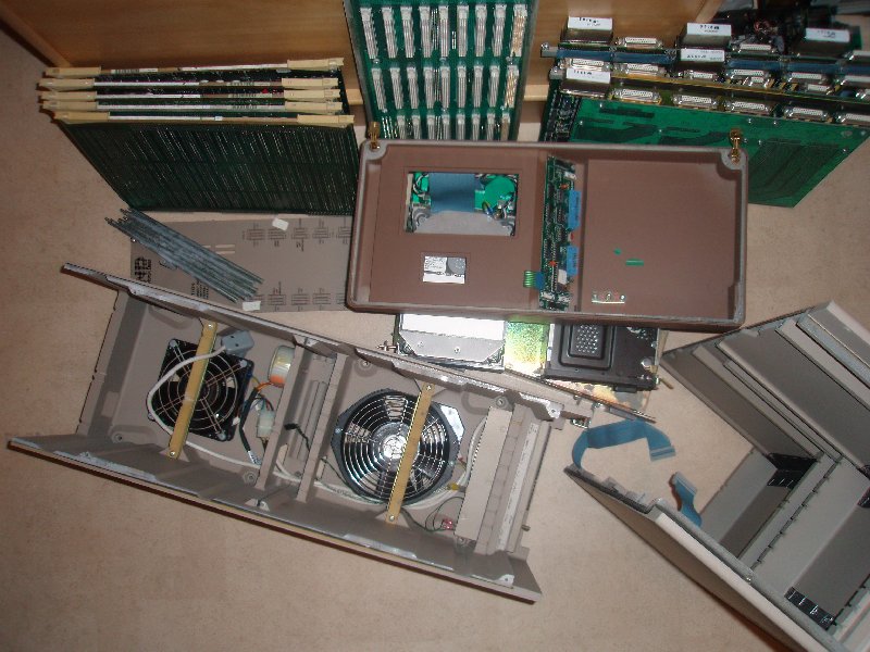
From this pile of trash I will now try to restore all the parts and rebuild the entire ND Satellite, making it run again after all these years. All parts must be restored and verified one by one, until we again (hopefully) can apply power to the machine. The next sections will take us through the restore process, step by step, showing all the parts and what's done to them. |
|
|||||||||||||||||||||||||||||||||||||||||||||||||||||||||||||||||||||||||||||||||||||||||||||||||||||
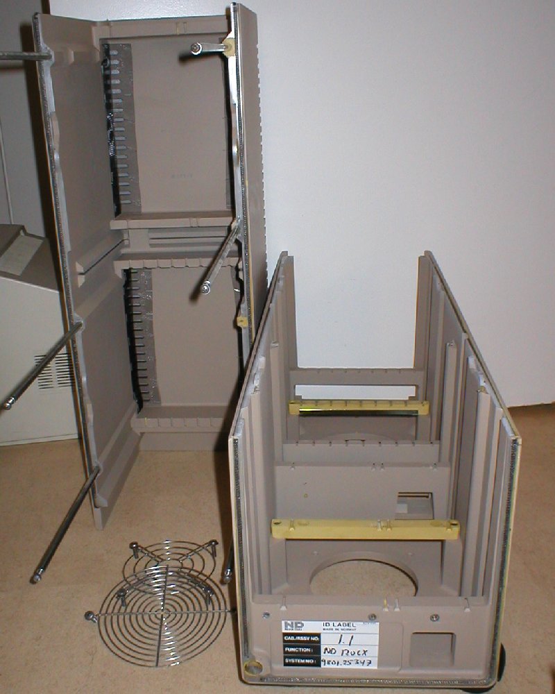
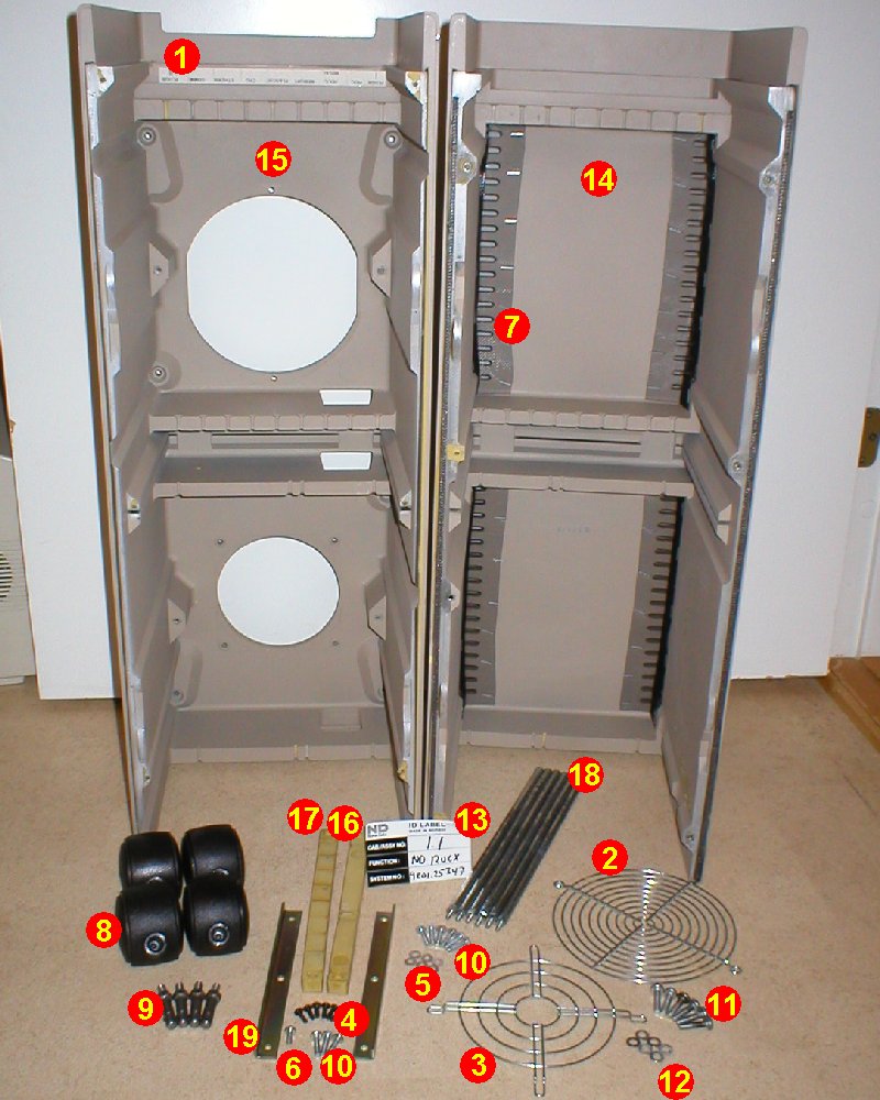
1 - The cabinetThe top and bottom cover are cleaned with soap and water, carefully so we don't scrub away the metallic edges of the cover reducing radio interference. Some scratches and marks are painted over with the color 12094 beige, a little glossy I think. The top cover at the ventilation holes has two pieces broken off; these are glued back on, nice. The micro mesh ribbons are cleaned for dust and the labels 509309 and 519681 are fixed back on with a little glue. The castors are cleaned and a drop of oil is applied to each axle, making the wheels roll nicely. The bolts are scrubbed for some rust and a small drop of oil is also added. The bolts are then fitted on the bottom cover and the castors are firmly pressed on. The treaded rods are polished for rust before they are mounted on the top cover. The top cover will be attached to the bottom with its screws later. A little rust is removed from one fan cover and screws before they are cleaned. The fan cover 510019 was too rusty so this one is replaced with another one. The covers will be mounted when we are ready with the fans in the next section. The guide stay for boards and disk with its angle piece and screws are just cleaned before inserted into the bottom cover. Note; the screw on the left side of 519705, are shorter than the other one. |
|
|||||||||||||||||||||||||||||||||||||||||||||||||||||||||||||||||||||||||||||||||||||||||||||||||||||
|
|
|||||||||||||||||||||||||||||||||||||||||||||||||||||||||||||||||||||||||||||||||||||||||||||||||||||
|
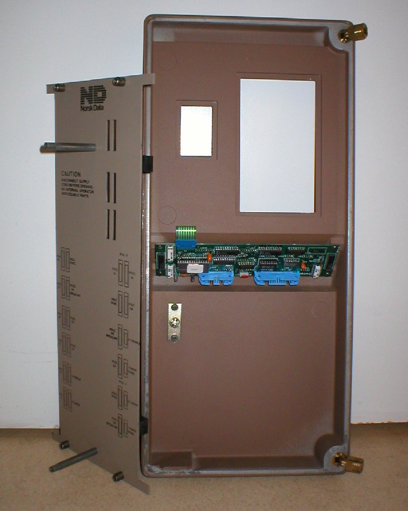
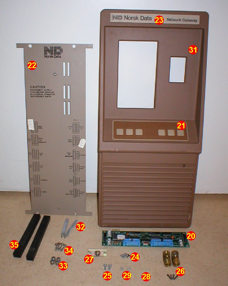
The back plate with its bolts, bushes and screws have a little rust removed and then they are cleaned. The pressure rubbers are attached with double coated tape on the back of the plate. The rubbers will put a gently pressure on all the PCBs keeping them steady in the card crate. We put the complete back plate aside, as it's one of the latest parts to be mounted on the machine. The front panel or door if you like, is cleaned with soap and water. The membrane switch is already glued to the door so don't make this wet while cleaning. There are some scratches on the door which are painted over with 12095 brown. The PCB 1834 Panel Control is just gently brushed removing any dust, as it can't be washed of course. All the screws, hinges and the lock are cleaned, removing some rust. Two of the small locking screws for the hinge were very rusty, some serious cleaning was necessary. All the parts are mounted back on to the door and put aside as the door can't be mounted until top cover is placed back on. |
|
|||||||||||||||||||||||||||||||||||||||||||||||||||||||||||||||||||||||||||||||||||||||||||||||||||||
|
|
|||||||||||||||||||||||||||||||||||||||||||||||||||||||||||||||||||||||||||||||||||||||||||||||||||||
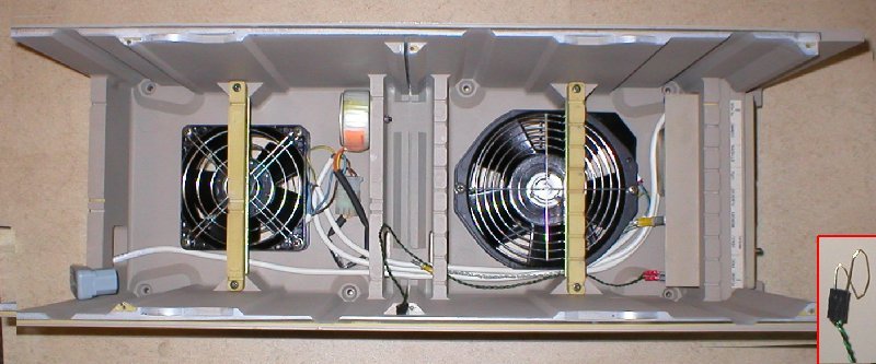
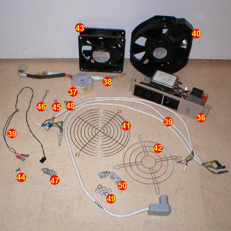
2 - The 230V AC power distributionBoth fans are cleaned with a moist cloth, removing all the dust and dirt. The same is done to the all the cables, gently cleaning them with a moist cloth. Alt the screws, washers, nuts and the fan cover have a little rust removed and then they are cleaned. The fan cover 510019 on the inside was too rusty so it's replaced. The line module and trafo are just brushed for any dust, and checked for any visible damage. Connect all the cables to the line module before mounting it into the bottom cover. Now connect the cables to both fans before they are mounted in there place, remember the outside fan covers. Now it's time to mount the inside fan covers. The trafo is put in place and connected and all cables are placed nicely. Now we can start the testing with the power on. Connect the power line and turn the main switch on, nothing happens. The key switch on the power supply must to turn on, but this part isn't ready yet. Too make things happen we need a little help from a paper clip, shorting the key switch connector (see small picture). The relays on the line module now switch the main AC power on and both the fans start spinning. Great! |
|
|||||||||||||||||||||||||||||||||||||||||||||||||||||||||||||||||||||||||||||||||||||||||||||||||||||
|
|
|||||||||||||||||||||||||||||||||||||||||||||||||||||||||||||||||||||||||||||||||||||||||||||||||||||
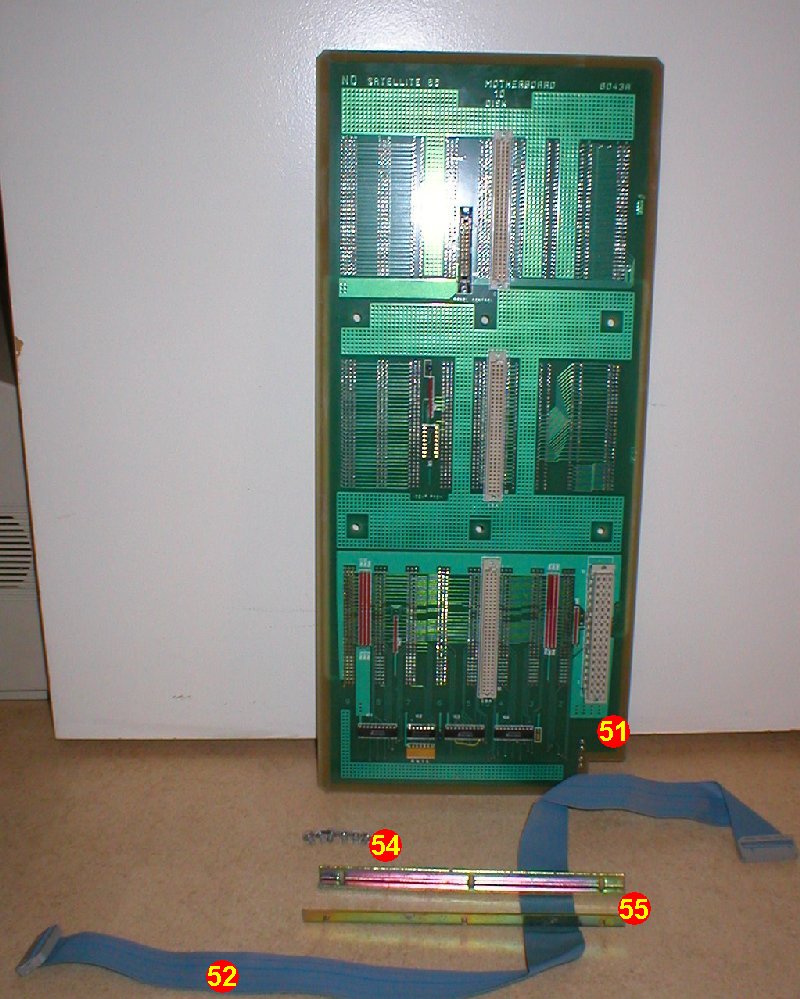
3 - The motherboardThe motherboard is carefully brushed for any dust and gently cleaned with a moist cloth on the edges. Now we have a close inspection of any visible damages to the board itself and all its connectors. None damages can be found, every thing looks nice. The screws and angle pieces are clean for a little bit of rust and restored to the board. The motherboard can now be inserted into its slot in the middle of the cabinet. Connect the grounding cable from the line module and also the key switch cable. Make sure that the negative (black) wire of the key switch cable is down. Every thing inside the cabinet is now in place and the top cover can be mounted. The front door will also be fixed to the cabinet and now it start to look like a ND Satellite again. At last insert the operator panel cable and secure it to the inside of the cabinet with the double coated tape. |
|
|||||||||||||||||||||||||||||||||||||||||||||||||||||||||||||||||||||||||||||||||||||||||||||||||||||
|
|
|||||||||||||||||||||||||||||||||||||||||||||||||||||||||||||||||||||||||||||||||||||||||||||||||||||